

Professional Pressure Testing System Bulk Meter Test Bench
presure testing bench bulk meter
1.General
XBT50—100mm Water Meter Testing Bench, is made according to the national standard ZBY303—85 “DN50-400 Screw wheel cold potable water meter” and the national inspection rule JJG258-88 “Water meter and testing equipment inspection rules”. It adopts the principle of Volumetric Measurement. The bench is widely used to do error testing, error curve testing by water meter manufacturing & maintaining company, big & medium enterprise, Water Supply Corporation and standard measuring bureau. It features reasonable construction, high accuracy, long working life. Every bench must be tested by the standard measuring bureau, only the qualified can leave factory with issued certificate.
2.Technical Data
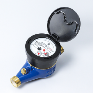
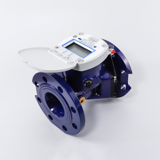
1. Size of Tested water meter: DN50,DN80,DN100
2. Accuracy: Grade Two.
3. Accumulative error: less than ±0.2%
4. Test Manner: Principle of Volumetric Measurement
5. Standard graduated cylinder:
Material: 1Cr18Ni9
Volume: 0.2m3、0.5m3、1m3、2m3
6. Instant Flow-rate Meter:
Flow-rate range: 0.2~18m3/h, 20~120 m3/h
7. Commutator:
Driving force: 0.4~0.6MPa Compressed gas
Commutate time: <400ms
Commutate time error: <60ms
8. Testing water pressure: 0.35-0.45Mpa
9. Power: 380V 50HZ
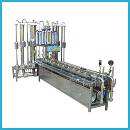
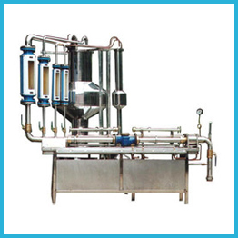
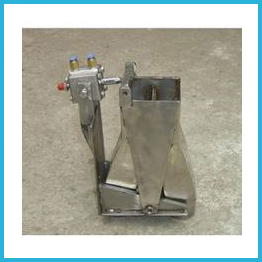
3.Working Principle
The bench consist of pneumatic butterfly valve, Straight pipeline, Clamp, Flow-rate adjusting valve, Instant flow-rate meter, Commutator, Standard graduated cylinder, Water level gauge, Water-out valve, electrical controller etcWater from source flow into Water supply butterfly valve, Straight pipeline, then through Clamp into Flow-rate adjusting valve and Instant flow-rate meter; next into the standard graduated cylinder. Write down the reading of the tested water meter and the reading of Standard graduated cylinder. Based on these two readings, the measurement errors can be calculated as the following formula:
E = (Vi–Vc)/Vc×100%
Attached Table :
SIZE | Permanent Flow-rate | Transitional Flow-rate | Minimum Flow-rate | |||
m3/h | m3 | m3/h | m3 | m3/h | m3 | |
50 | 15 | 0.5 | 4.5 | 0.2 | 1.2 | 1(0.2) |
3 | 0.45 | |||||
80 | 40 | 3 | 12 | 0.5 | 3.2 | 1(0.2) |
8 | 1.2 | |||||
100 | 60 | 3 | 18 | 0.5 | 4.8 | 1(0.2) |
12 | 1.8 | |||||
Error | ±2% | ±2%(±3%) | ±5% | |||
Note: Data in bracket mean the water meter is using or repaired.
4.Installing Requirements
1. Install at lighter and ventilation.
2. The water inlet pipe doesn’t little the main pipe of setting, no leakage and cleans.
3. Water pressure must stable, water quality must clean.
4. The setting must be installed horizontal; glass rotor flow-rate meter should be installed vertically, with gradient less than 5 degree.
5. Supply voltage variation is less than ±5%.
6. Power cord must three-phase four-wire system, the testing and the electrical controller must be earthing infallible.
7. Put the controller in proper place connect the power supply gas supply and manipulative wire.
5. Water Meter Testing Bench Operating Rules
1. Before testing, make sure the power and water supply run well, keep the bench in good working state. Examine the lift desk and ensure it come back the lowest. Examine the setting before running. (air compressor is operating, 0.4—0.8Mpa)
2. Power on, press the “release” button to withdraw the clamps. prevent clamp machine put out and mangle equipment. Push “0.5m3 gauging vessel open” or “2m3 gauging vessel open” to open the foot valve of the vessel tank. Shut off all flow-rate adjusting valve
3. Respectively fit the tested water meter and the corresponding straight pipeline mouth on both side of the clamp and the Rectifier. Keep the water meter at the lift desk, adjust the lift desk, and put the water meter and the straight pipeline at the same high.
4. Power on and the air compressor is running, when the pressure come to 4×10⁵Pa, Press button “CLAMP” to clamp the meter. Press MINOR VALVE“OPEN” to open the branch valve of inlet pipe, close other valve except the drain valve, close the drain valve when outflow water from it. Press MAIN VALVE “OPEN” to open the main valve of inlet pipe. When the pressure is same of pipe inside and outside about 2 minutes later.
5. Press button COMMUTATOR“ENTER” or “OUT” (or adjust the commutator valve handle on the bench) to switch the commutator to the vessel tank you do NOT choose, e.g. If you need use 2m3 tank for testing, then turn the commutator to the 0.5m3 tank. Close the foot valve of work meter.
6. Adjust the flow-rate slowly to the required value; Press GLOBE VALVE“OPEN”“CLOSE” to adjust high flow. Press 2m3 or 0.5m3 gauging vessel “Close” to close the foot valve of work meter. Watch the pointer of the water meter, write down the reading you tested, press button COMMUTATOR“ENTER” or “OUT” to switch the commutator to the vessel tank you work . When the water meter passed the required amount of water, switch the commutator to out at the same time, close the flow-rate adjusting valve, (liquid cylinder readings should wait until the water level surface become smooth)
7. Press the button 0.5m3 GAUGING VESSEL“CLOSE” (or 2m3 GAUGING VESSEL“CLOSE”) to close the foot drain valve.
8. Write down the reading of the water meter and calculate the measurement error according to the formula. Repeat xi and xii if need to test another flow rate.
9. After testing, Press MAIN VALVE“CLOSE” to close the main valve of inlet pipe, Press RELEASE VALVE “OPEN”to open the drain valve, when the pressure gauge point to zero, press RELEASE VALVE “CLOSE” to close the drain valve, then press CLAMPING DEVICE “RELEASE” to take out the water meter, finally back off the clamp machine and take down the water meter. Repeat step I to xiv to test another water meter.
10. In the end, empty the water in all pipes and flow meters; turn off the power of controller and the main power.
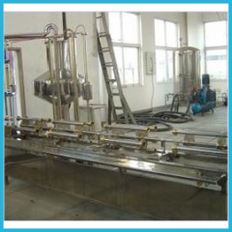
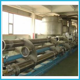
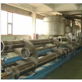
Factory Show